The structural analysis software RFEM 6 is the basis of a modular software system. The main program RFEM 6 is used to define structures, materials, and loads of planar and spatial structural systems consisting of plates, walls, shells, and members. The program also allows you to create combined structures as well as to model solid and contact elements.
RSTAB 9 is a powerful analysis and design software for 3D beam, frame, or truss structure calculations, reflecting the current state of the art and helping structural engineers meet requirements in modern civil engineering.
Do you often spend too long calculating cross-sections? Dlubal Software and the RSECTION stand-alone program facilitate your work by determining section properties of various cross-sections and performing a subsequent stress analysis.
Do you always know where the wind is blowing from? From the direction of innovation, of course! With RWIND 2, you have a program at your side that uses a digital wind tunnel for the numerical simulation of wind flows. The program simulates these flows around any building geometry and determines the wind loads on the surfaces.
Are you looking for an overview of snow load zones, wind zones, and seismic zones? Then you are in the right place. Use the Geo-Zone Tool to determine quickly and efficiently snow loads, wind speeds, and seismic data according to ASCE 7‑16 and other international standards.
Would you like to try out the capabilities of the Dlubal Software programs? You have the opportunity to do so! The free 90-day full version allows you to thoroughly test all our programs.
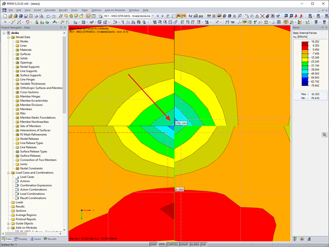
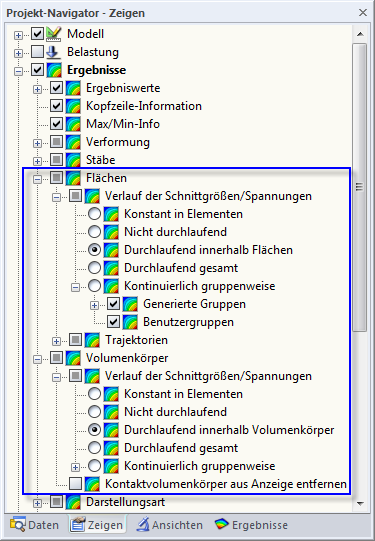
The FE analysis determines the results for each FE mesh node. Usually, continuous distribution of the internal force or deformation is preferable for the graphic. For this purpose, it is necessary to smooth the results; for example, via interpolation. However, the question cannot be answered in general, as this has to be decided from model to model. Basically, RFEM distinguishes between the following five options:
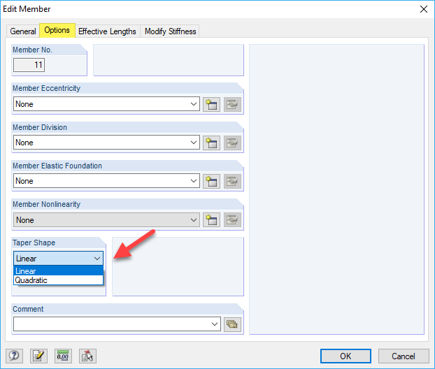
RFEM and RSTAB interpolate the variable stiffnesses along the member by higher-order polynomials. The internal determination of tapered cross-sections is done using the taper shape (see Image 01). If different cross-sections are defined for the member start and end, you can select the "linear" or "quadratic" taper shape. This way, it is possible to represent the taper geometry for the determination of the interpolated cross-section properties.
In most cases, the layout of the taper is linear; that is, the member only tapers and extends regularly over the depth of the start to the end section. However, if the cross-section width and depth change, the quadratic shape is recommended for the interpolation of the cross-section properties.
For more precise results, it can also be reasonable to divide the tapered member and create additional cross-sections.
The calculation of tapered members is also influenced by the division for tapered and foundation members, which is managed in the calculation parameters (see Image 02).